For the next-generation in-vehicle networking infrastructure beyond CAN and FlexRay, the automotive industry has identified Ethernet as a very promising candidate. Ethernet being an IEEE standard and commonly used in consumer and industry domains provides a high re-use factor for components, software and tools.
In addition, Ethernet has the bandwidth capability that is required for new driver assistance and infotainment systems, for example. However, to become a success story, solutions for the automotive industry have to be further optimised in terms of scalability, low cost, low power and robustness.
The first optimisation steps on the physical layer level have already been taken but more innovation needs to be focused on automotive use cases. This paper discusses new network topologies and components and describes an evolutionary path of Ethernet into automotive applications.
Communication and bandwidth requirements increase as more and more new, complex applications appear in the car, for example for enhanced safety and entertainment solutions. End users expect the same level of entertainment functions in the car as known from their home environment.
Furthermore, existing vehicle control networks like the LIN, CAN and FlexRay standards are not designed to cover these increasing demands in terms of bandwidth and scalability that we see with various kinds of Driver Assistance Systems (DAS).
Future networking technology should re-use as much as possible from consumer and other non-automotive domains, while taking into account the automotive-specific requirements.
(From left to right: Peter Hank, Thomas Suermann, Steffen Müller)
This includes hardware components as well as software stacks. Communication solutions for higher bandwidth, such as MOST, are available but expensive for a broader usage in automotive networking systems. Today, in-vehicle networking architecture appears as a heterogeneous system as a result of its historically grown nature(see the left schematic in Fig. 1).
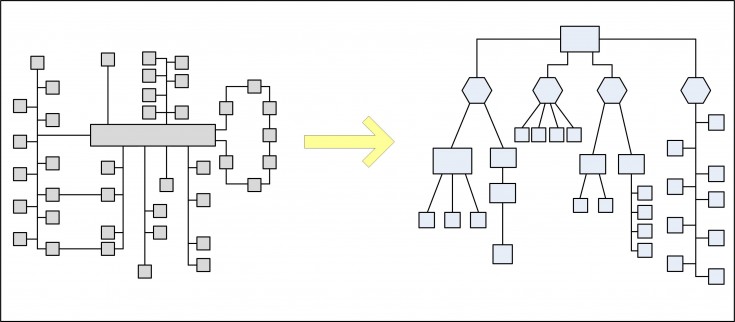
A new in-vehicle networking system built from scratch and without legacy would most likely have the architecture as shown in the right schematic of Fig. 1. Here, ECUs are structured in a hierarchical architecture where application domains are connected through a data highway.
Ethernet provides all the prerequisites for such a holistic approach. It could be used as a backbone bus to connect the various application domains as well as for sub-networks that just require higher bandwidth.
Today, switched Ethernet networks rely on a point-to-point communication where the available bandwidth is more efficiently used compared to broadcast systems like CAN or FlexRay. The switching concept can be advantageously applied to bridge the domain boundaries without time-consuming packing and re-sorting of the transmitted messages or packages as needed in a complex gateway.
The usage of Ethernet in the car means a paradigm shift in the design of next-generation in-vehicle networking systems: connecting different domain networks, transporting different kinds of data (control data, streaming, etc.) and fulfilling the stringent robustness demands in terms of extended temperature range and EMC performance.
Evolution towards Automotive Ethernet
Ethernet is an open LAN standard and defines the two lower layers of the OSI reference model. Over the past decades, the IEEE 802 standardisation committee has specified several physical layers from 10Mbps up to 10Gbps. IEEE 802.3u (100Base-TX) is widely used in consumer and industrial domains and has recently been selected for car diagnostics over IP as described in ISO 13400.
Higher layers have to be taken into account besides data link and physical layer, as shown in Fig. 2. The Audio/Video Bridging (AVB) Task Group of AVnu alliance [1] has defined IEEE standards covering higher-level services for IEEE 802-compliant networks.
The protocols IEEE 802.1 AS, QAT, QAV and BA cover address timing and synchronisation, streaming reservation, forwarding and queuing in Audio/Video Bridging systems. In addition, transport protocol layer standards like IEEE 1722 facilitate stream-time-sensitive audio and/or video across Ethernet AVB networks and interoperability between end stations.
Driver Assistance Systems are increasingly using video cameras for applications like surround view. Activities for the standardisation of the communication protocol and physical layer have recently been started in ISO 17215 called “Video Communication Interface for Cameras”.
In order to further develop the Automotive Ethernet technology, an industry-wide Special Interest Group named One Pair EtherNet Alliance has been formed for the physical layer. The so-called “OPEN Alliance” will work on standardisation for components and compliance tests based on the Broadcom BroadR-Reach technology [2].
A further intention of the interest group is to gather requirements for future technologies such as “Reduced Pair Gigabit”. Finally AUTOSAR addresses Automotive Ethernet in their software layer stack.
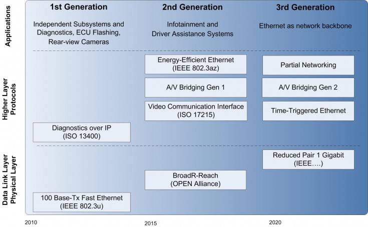
Ethernet has not been developed for TDMA networking and one topic that still needs to be addressed for automotive systems is a suitable solution to achieve the required real-time performance and Quality of Service. AVB already includes measures to ensure the timely delivery of media streams.
For the Automotive AVB Gen2 Work Group, latency time improvements are one of the major targets. First applications for Time-Triggered Ethernet took place in Avionic systems [3] with highest safety level requirements. Defined in SAE AS6802 and different to Audio/Video Bridging, TTEthernet is based on a distributed clock-synchronisation algorithm that finally results in an exact schedule with deterministic behaviour.
Although the integration of both AVB and TTEthernet is possible [4], further investigations are needed to allow its use in automotive applications where multimedia streams, real-time control data as well as diagnostic information and software updates will be transmitted on the same network.
Generation 1: Diagnostics over IP
The first Ethernet applications for the automotive industry are On-Board Diagnostics (OBD) and the update of ECU flash memories. For the reading-out of diagnostics data and the updating of software within a given time frame, the performance of existing in-vehicle bus systems such as CAN and FlexRay was not sufficient.
Ethernet 100Base-TX with CAT 5 has been chosen for the interface between the vehicle and the diagnostics test equipment. The higher bandwidth of Ethernet saves costs in service and production.
ISO 13400 and ISO 14229 utilise existing industry standards and define a long-term stable state-of-the-art diagnostics standard. Products and components are already available from versatile suppliers as automotive requirements such as robustness and temperature tolerances have been relaxed for this specific use case.
Generation 2: Driver Assistance Systems and Infotainment
The second generation of Automotive Ethernet will address infotainment and camera systems for surround view applications. Today’s rear-view camera solutions often use LVDS for the transfer of video data, which works well for single cameras. In future systems, this will consist of more cameras and fuse with sensor data from short/long-range radar, for example (Fig. 3).
An LVDS-based system becomes inefficient in terms of wiring harness and expensive cables and connectors. Switched Ethernet allows video cameras to be connected to a central control unit for synchronisation and further processing.
Ethernet cameras can further benefit from “Energy-Efficient Ethernet” (IEEE 802.3az), which introduces a Low- Power Idle (LPI) mode and wake-up functionality to save energy when the cameras are not being used. Additionally, solutions for Power over Ethernet (PoE) are preferred to further reduce wiring harness.
The demand for higher bandwidth and lower latency is obvious. Multiple high-resolution cameras for uses such as object detection require uncompressed data transfers, for example to avoid compression artefacts for obstacle detection, and are a strong driver of higher bandwidth.
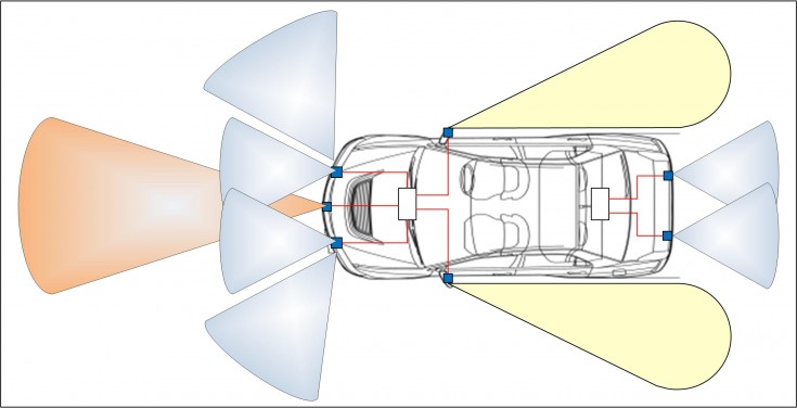
Recent infotainment solutions are mainly based on proprietary and non-scalable technologies. Automotive Ethernet addresses this emerging application field in a cost-effective manner by making use of the AVB standard. Synchronised transmission of video and audio data with guaranteed latency can already be achieved with existing AVB Gen 1 Ethernet components.
However, both applications fields will benefit from current AVnu standardisation activities and the most recent Switch and PHY developments based on the BroadR-Reach physical layer.
Generation 3: Ethernet as network backbone
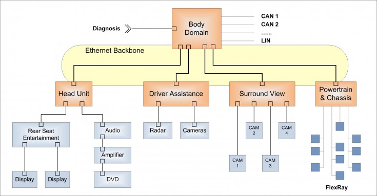
While for generation 1 and 2 Ethernet remains confined to subnets of certain applications like infotainment and driver assistance, with generation 3 Ethernet will become the backbone of the in-vehicle network. A typical backbone is illustrated in Fig. 4. The design of such a network will be a paradigm shift in the way communication between ECUs has to be organised by the network management.
The communication network will be organised in a highly hierarchical way with the main domain controllers connected via an Ethernet backbone. Sub-networks below the domain controllers may be Ethernet-based, too, with switches bridging between the network levels.
This structure provides a scalable solution as each port of a switch can in general be implemented as 10Mbps, 100Mbps or 1Gbps without any changes to higher protocol layers. The paradigm shift also becomes visible in how a message is transferred via possible domain boundaries to its destination. While in today’s networks complex and network-dependent gateways realise this function, known and mature IP-based routing within switches and routers are proposed for backbone networks.
The advantage is that IP routing is fully independent of the underlying network implementation, thus allowing a homogeneous addressing concept for the whole in-vehicle network. Moreover, the IP concept enables the straightforward connection of the car infrastructure to the Internet [5], a trend which is mainly driven by end users expecting the same access to services provided by the Internet as known from home.
A further characteristic of the new architecture is that in principle there will be one backbone network technology only, namely Ethernet, which has to accommodate different data communication classes like diagnostics, video/audio streaming and highly dependable control data. While AVB Ethernet and TTEthernet can already provide different levels of Quality of Service (QoS) combined with real-time performance, further R&D activities are needed to validate the secure coexistence of these different data communication classes on the same network.
BroadR-Reach – a 100Mbps Automotive Ethernet solution
Though 100Mbps Ethernet and IP technology has been available since the early 1990s, it took Ethernet almost 20 years to attract the interest of the automotive industry as a next-generation in-vehicle networking standard. This was partly because of the lack of a physical layer suitable for use in vehicles.
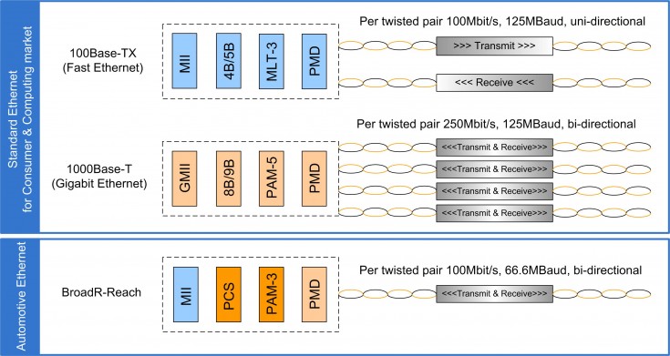
Fig. 5 illustrates the technical principles in more detail and explains why the consumer-oriented physical layers of Fast and Gigabit Ethernet did not make it into the car. Fast Ethernet is based on a MLT-3 signalling scheme (distinguishing three levels +/0/-) and features a uni-directional communication on two twisted pairs of cable.
Gigabit achieves 10x higher data rate by introducing a bi-directional communication on four twisted pairs of cable and a PAM-5-based signalling scheme. To compensate for the 6 dB signal-to-noise loss of the PAM-5 versus the MLT-3 signalling, a costly error forward correction code (Trellis) has to be employed.
The high symbol rate of 125 MBaud for both Fast and Gigabit Ethernet makes a significant contribution to electromagnetic emissions in the critical FM radio band and thus rules out the use of inexpensive unshielded twisted pair cable in an automotive environment. The BroadR-Reach technology has managed to almost halve the symbol rate to 66.6 MBaud and paved the way for the use of unshielded twisted-pair cable.
In principle, BroadR-Reach can be regarded as a “light version” of Gigabit, adopting the bi-directional communication scheme while requiring only one pair of cables. Thanks to the PAM-3 signalling, a bit error rate of less than 10-10 can be achieved even without error forward correction.
Automotive applications impose considerably higher requirements on electronic systems and their components compared to the consumer world, mainly in terms of EMC [ISO11452] and environmental conditions. First investigations indicated that BroadR-Reach is suitable for use in the automotive environment.
However, to achieve the robustness needed for a next-generation in-vehicle networking standard, new optimised components need to be developed. The system diagram in Fig. 6 reveals the main components of an automotive BroadR-Reach link. Compared to standard Fast Ethernet, the bill of material could be significantly reduced.
Applying a capacitive coupling instead of a conventional transformer, the physical layer hardware effort – consisting of PHY, common mode choke (CMC), coupling capacitors, connector and UTP cable – is very similar to a FlexRay or CAN link.

The PHY as the interface between the analogue transmission medium and the digital MAC controller largely determines the robustness and emission performance of a link. While a consumer PHY is optimised to support a cable length of more than 100 m, automotive PHYs typically have to deal with a link length of less than 10 m.
The challenge here is to find a pulse shaping and receiver equalizer implementation optimised for such a cable length that can meet the stringent automotive emission and immunity requirements.
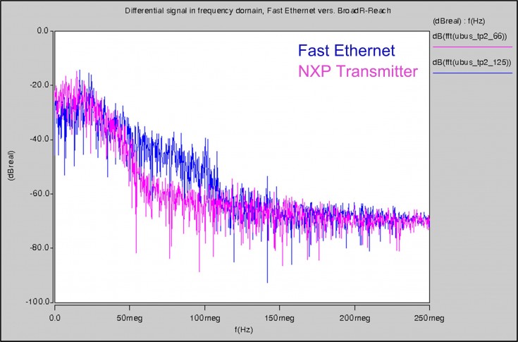
Fig. 7 shows the signal spectrum of the NXP transmitter concept with optimised pulse shaping, indicating that the automotive emission requirements can be met without the use of expensive low-pass filter components. For comparison, the corresponding signal spectrum of a Fast Ethernet transmitter reveals higher signal energy in the critical FM radio band.
The BroadR-Reach technology allowing the usage of unshielded twisted-pair cable makes Ethernet cost-competitive for automotive applications. Since FlexRay cable is able to cope with harsh automotive environmental conditions it is the first choice for Automotive Ethernet, too.
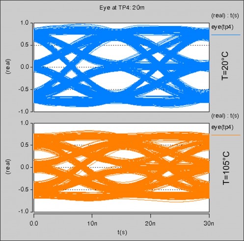
In contrast to consumer applications, a careful study of the impact of environmental conditions (mainly temperature) on the Ethernet signal integrity is needed. Fig. 8 compares the simulated eye pattern for a 20 m FlexRay cable at room temperature with that at an elevated cable temperature of 105°C.
The smaller eye opening for high temperatures indicates rising Inter-Symbol Interference (ISI) as a result of cable bandwidth limitations. As long as the cable length is kept below 20 m, the reduced signal-to-noise ratio can be typically compensated by adaptive equalisation in the receiver without compromising the bit error rate.
With BroadR-Reach, a physical layer suitable for use in the automotive field is available which is cost-effective and can meet the main automotive requirements in terms of EMC, robustness and environmental conditions. In order to deploy the full potential of the BroadR-Reach technology, the development of dedicated automotive PHYs and common mode chokes is encouraged.
